 WHAT IS DIGITAL LOGIC
Digital logic is the representation of signals and sequences of a digital circuit through numbers. It is the basis for digital computing and provides a fundamental understanding on how circuits and hardware communicate within a computer. Digital logic is typically embedded into most electronic devices including calculators, computers, video games and watches.
TYPE OF LOGIC GATESAND GATES
And gates is when two input will divide with each other to get their output.Example if input A is 0 then input B O,then input A and input B will divide and get 0 for the output.The example as below:-

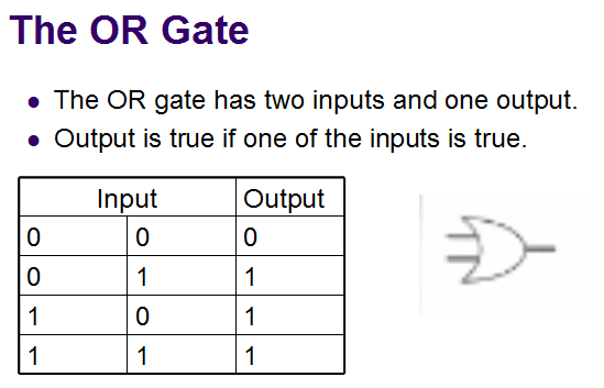
OR Gates
NOT Gates

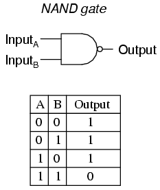
NAND Gates
NAND Gates is combination of AND gates and NOT gates.Firstly the both input will divide then the output will change to other such as when the output get 1 it will change to 0.
NOR GATES
NOR Gates is combination of OR gates and NOT gates.Firstly the both input will divide then the output will change to other such as when the output get 1 it will change to 0.

XOR GATES
 SIMPLICATION OF BOOLEAN EQUATION
 Laws of boolean algebra
Truth Tables for the Laws of Boolean
| Boolean Expression | Description | Equivalent Switching Circuit | Boolean Algebra Law or Rule |
| A + 1 = 1 | A in parallel with closed = "CLOSED" |  | Annulment |
| A + 0 = A | A in parallel with open = "A" |  | Identity |
| A . 1 = A | A in series with closed = "A" |  | Identity |
| A . 0 = 0 | A in series with open = "OPEN" |  | Annulment |
| A + A = A | A in parallel with A = "A" |  | Indempotent |
| A . A = A | A in series with A = "A" |  | Indempotent |
| NOT A = A | NOT NOT A (double negative) = "A" | Double Negation | |
| A + A = 1 | A in parallel with not A = "CLOSED" |  | Complement |
| A . A = 0 | A in series with not A = "OPEN" |  | Complement |
| A+B = B+A | A in parallel with B = B in parallel with A |  | Commutative |
| A.B = B.A | A in series with B = B in series with A |  | Commutative |
| A+B = A.B | invert and replace OR with AND | de Morgan’s Theorem | |
| A.B = A+B | invert and replace AND with OR | de Morgan’s Theorem |
Description of the Laws of Boolean Algebra
- Annulment Law – A term AND´ed with a “0” equals 0 or OR´ed with a “1” will equal 1.
-
- A . 0 = 0, A variable AND’ed with 0 is always equal to 0.
- A + 1 = 1, A variable OR’ed with 1 is always equal to 1.
- Identity Law – A term OR´ed with a “0” or AND´ed with a “1” will always equal that term.
-
- A + 0 = A, A variable OR’ed with 0 is always equal to the variable.
- A . 1 = A, A variable AND’ed with 1 is always equal to the variable.
- Indempotent Law – An input AND´ed with itself or OR´ed with itself is equal to that input.
-
- A + A = A, A variable OR’ed with itself is always equal to the variable.
- A . A = A, A variable AND’ed with itself is always equal to the variable.
- Complement Law – A term AND´ed with its complement equals “0” and a term OR´ed with its complement equals “1”.
-
- A . A = 0, A variable AND’ed with its complement is always equal to 0.
- A + A = 1, A variable OR’ed with its complement is always equal to 1.
- Commutative Law – The order of application of two separate terms is not important.
-
- A . B = B . A, The order in which two variables are AND’ed makes no difference.
- A + B = B + A, The order in which two variables are OR’ed makes no difference.
- Double Negation Law – A term that is inverted twice is equal to the original term.
-
- A = A, A double complement of a variable is always equal to the variable.
- de Morgan´s Theorem – There are two “de Morgan´s” rules or theorems,
- (1) Two separate terms NOR´ed together is the same as the two terms inverted (Complement) and AND´ed for example, A+B = A. B.
- (2) Two separate terms NAND´ed together is the same as the two terms inverted (Complement) and OR´ed for example, A.B = A +B.
Other algebraic laws not detailed above include:
- Distributive Law – This law permits the multiplying or factoring out of an expression.
- Absorptive Law – This law enables a reduction in a complicated expression to a simpler one by absorbing like terms.
- Associative Law – This law allows the removal of brackets from an expression and regrouping of the variables.
Boolean Algebra ExampleBoolean Algebra Example No1
Construct a Truth Table for the logical functions at points C, D and Q in the following circuit and identify a single logic gate that can be used to replace the whole circuit.
First observations tell us that the circuit consists of a 2-input NAND gate, a 2-input EX-OR gate and finally a 2-input EX-NOR gate at the output. As there are only 2 inputs to the circuit labelled A and B, there can only be 4 possible combinations of the input ( 22 ) and these are: 0-0, 0-1, 1-0 and finally1-1. Plotting the logical functions from each gate in tabular form will give us the following truth table for the whole of the logic circuit below.
| Inputs | Output at | |||
| A | B | C | D | Q |
| 0 | 0 | 1 | 0 | 0 |
| 0 | 1 | 1 | 1 | 1 |
| 1 | 0 | 1 | 1 | 1 |
| 1 | 1 | 0 | 0 | 1 |
From the truth table above, column C represents the output function generated by the NAND gate, while column D represents the output function from the Ex-OR gate. Both of these two output expressions then become the input condition for the Ex-NOR gate at the output.
It can be seen from the truth table that an output at Q is present when any of the two inputs A or Bare at logic 1. The only truth table that satisfies this condition is that of an OR Gate. Therefore, the whole of the above circuit can be replaced by just one single 2-input OR Gate.
Boolean Algebra Example No2
Find the Boolean algebra expression for the following system.

The system consists of an AND Gate, a NOR Gate and finally an OR Gate. The expression for theAND gate is A.B, and the expression for the NOR gate is A+B. Both these expressions are also separate inputs to the OR gate which is defined as A+B. Thus the final output expression is given as:

The output of the system is given as Q = (A.B) + (A+B), but the notation A+B is the same as the De Morgan´s notation A.B, Then substituting A.B into the output expression gives us a final output notation of Q = (A.B)+(A.B), which is the Boolean notation for an Exclusive-NOR Gate as seen in the previous section.
| Inputs | Intermediates | Output | ||
| B | A | A.B | A + B | Q |
| 0 | 0 | 0 | 1 | 1 |
| 0 | 1 | 0 | 0 | 0 |
| 1 | 0 | 0 | 0 | 0 |
| 1 | 1 | 1 | 0 | 1 |
Then, the whole circuit above can be replaced by just one single Exclusive-NOR Gate and indeed anExclusive-NOR Gate is made up of these individual gate functions.
Boolean Algebra Example No3
Find the Boolean algebra expression for the following system.

This system may look more complicated than the other two to analyse but again, the logic circuit just consists of simple AND, OR and NOT gates connected together.
As with the previous Boolean examples, we can simplify the circuit by writing down the Boolean notation for each logic gate function in turn in order to give us a final expression for the output atQ.

The output from the 3-input AND gate is only at logic “1” when ALL the gates inputs are HIGH at logic level “1” (A.B.C). The output from the lower OR gate is only a “1” when one or both inputs B orC are at logic level “0”. The output from the 2-input AND gate is a “1” when input A is a “1” and inputs B or C are at “0”. Then the output at Q is only a “1” when inputs A.B.C equal “1” or A is equal to “1” and both inputs B or C equal “0”, A.(B+C).
By using “de Morgan’s theorem” inputs B and input C cancel out as to produce an output at Q they can be either at logic “1” or at logic “0”. Then this just leaves input A as the only input needed to give an output at Q as shown in the table below.
| Inputs | Intermediates | Output | ||||||
| C | B | A | A.B.C | B | C | B+C | A.(B+C) | Q |
| 0 | 0 | 0 | 0 | 1 | 1 | 1 | 0 | 0 |
| 0 | 0 | 1 | 0 | 1 | 1 | 1 | 1 | 1 |
| 0 | 1 | 0 | 0 | 0 | 1 | 1 | 0 | 0 |
| 0 | 1 | 1 | 0 | 0 | 1 | 1 | 1 | 1 |
| 1 | 0 | 0 | 0 | 1 | 0 | 1 | 0 | 0 |
| 1 | 0 | 1 | 0 | 1 | 0 | 1 | 1 | 1 |
| 1 | 1 | 0 | 0 | 0 | 0 | 0 | 0 | 0 |
| 1 | 1 | 1 | 1 | 0 | 0 | 0 | 0 | 1 |
Then we can see that the entire logic circuit above can be replaced by just one single input labelledA thereby reducing a circuit of six individual logic gates to just one single piece of wire, (or Buffer). This type of circuit analysis using Boolean Algebra can be very powerful and quickly identify any unnecessary logic gates within a digital logic design thereby reducing the number of gates required, the power consumption of the circuit and of course the cost.
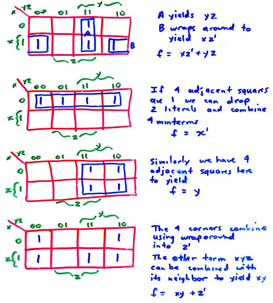
 KARNAUGH MAP
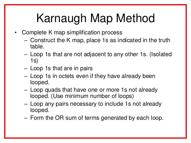

 m(0); K = 0


 SOURCE
*https://www.google.com.my/search?q=and+gates+bergerak&biw=1366&bih=667&source=lnms&tbm=isch&sa=X&ei=JY91VNXHKJCLuATzrICICA&ved=0CAYQ_AUoAQ#tbm=isch&q=karnaugh+map+examples+with+solutions&imgdii=_
*http://en.wikipedia.org/wiki/Karnaugh_map
*http://www.electronics-tutorials.ws/boolean/bool_6.html
*http://www.facstaff.bucknell.edu/mastascu/elessonshtml/logic/logic1.html

No comments:
Post a Comment